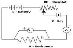
Ohm’s Law Verification can be done using instruments like Voltmeter and Ammeter. Apart from them for verification of Ohm’s law, we need some more apparatus like conducting wire, resistance, battery, rheostat, on/of switch or key, etc.
Ohm’s Law Statement
We already know the statement of Ohm’s Law which is
“If the physical state of the conductor (Temperature and mechanical strain etc.) remains unchanged, then the current flowing through a conductor is always directly proportional to the potential difference across the two ends of the conductor”
Mathematically
$V=IR$
where the constant of proportionality $R$ is called the electric resistance or simply resistance of the conductor. The following I vs V graph shows the relationship between current and voltage when resistance is constant;
Verification of Ohm’s law graph
The graph below illustrates the relationship between current and voltage for Ohm’s Law. You must collect experimental data, which includes various current and voltage values. Then you must plot this data to determine whether or not the apparatus you are using verifies Ohm’s Law. Obviously, you’d have to find the lowest count of both the ammeter and voltmeter for the purpose of accounting for apparatus errors.

Ohm’s Law can be verified if we manage to show that for a given conductor (a piece of wire) the ratio $V:I$ is constant. Resistance of the conductor is a constant for a known temperature range.
Experiment to verify ohm’s law
To verify this law you can set up a circuit with resistors of fixed values, a variable voltage source, a voltmeter, and an ammeter as shown below in the figure

Take one resistor, and connect a voltmeter parallel to it and an ammeter in series to the resistor and the voltage source.
Change the voltage by changing the resistance of variable resistance or rheostat.
Take the reading from the voltmeter and the corresponding current reading from the ammeter.
Plot a graph with voltages along X-axis and current along Y-axis. You should get a straight line of the form y = mx
Repeat the same taking different values of resistors. ‘m’ will be different for different resistances.
The Ohm’s will be verified if, for each value of resistances, the V-I graph is of the form $y = mx$. That is a straight line passing through the origin, making an angle with the axes.

ram
Thnx
i will try to do the practical, I hope the circuit will work
thanks
thanks