Electrical circuits are one of the most important things that govern the working of any device that runs on electricity. Circuits are the pathways that guide the powerful electric current to your homes and the electronic devices making them truly functional. The electrical circuits are hugely based upon two types of combinations which are ‘Parallel’ and ‘Series’.
In this article, we are going to see the working of parallel combinations of various electrical components in a circuit. Here we will discuss the parallel combination of components like
- Resistors
- Capacitors and
- Inductors
Parallel Circuit Definition
In ‘Electrical Engineering’ parallel circuits mean that the components used in the circuit are present in a parallel combination. But what does it mean when the components are in a parallel combination…?
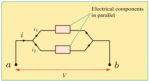
Well, this can be understood further with the help of the following figure and the statements accompanying with it which lists characteristics of parallel circuit,

Please note that electric components in the above figure can be resistors, inductors, capacitors, batteries, or switch depending on the requirement of the circuit.
Characteristics of Parallel Circuit
- In parallel combination, the components (resistors, capacitors, inductors, etc.) possess a common potential difference across their ends.
- With the same potential difference, the components also possess identical polarities (either positive or negative) at their ends.
- The charges in parallel combination circuits will pass in such a way that each charge will pass through one component only and will return to the other end. This phenomenon is totally opposite to what happens in the series combination.
- All components connected in the parallel combination will have the same voltage across them no matter what.
- The current through $a$ will be divided as it passes through the components and later will be summed up when the current reaches point $b$ according to Kirchhoff’s law.
Example Circuits
Let us now look at parallel combination of some electrical components one by one.
(A) For Resistors
Formula to remember $V = IR$

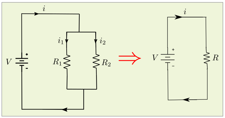
In the figure above, the two resistors with resistances $R_1$ and $R_2$ are connected in parallel. The voltage across each of them is $V$ and the current flowing through $R_1$ and $R_2$ is $i_1$ and $i_2$ respectively.
Here,
$i=i_1+i_2$
Let R be the equivalent resistance which can be assumed from the right-hand side figure.
From the formula, we have
$i=\frac{V}{R}$
$i_1 =\frac{V}{R_1}$
and
$i_2=\frac{V}{R_2}$
From the 2 equations above we can derive the formula for equivalent resistance which is,
$\frac{1}{R} =\frac{1}{R_1} +\frac{1}{R_2}$
Therefore, for $n$ resistors connected in parallel, the equivalent resistance would be,
$\frac{1}{R} =\frac{1}{R_1} +\frac{1}{R_2}+\frac{1}{R_3}+\ \ldots\ +\frac{1}{R_n}$
(B) For Capacitors
Formula to remember $q = CV$

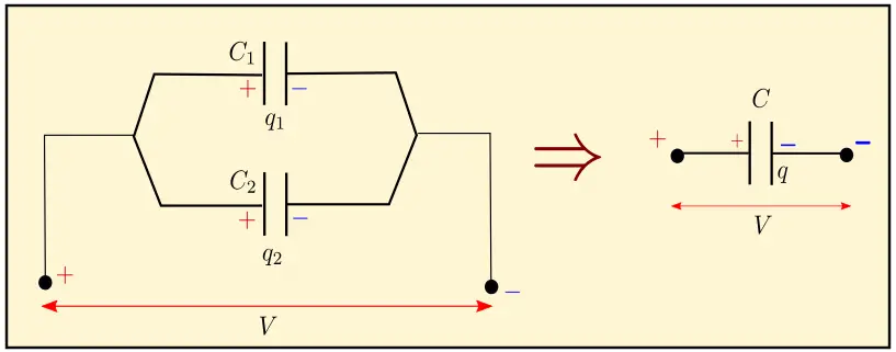
The above figure shows two capacitors with capacitance $C_1$ and $C_2$ in parallel combination. The voltage between them is $V$ and the total charge is distributed on the capacitors according to their capacitance.
So,
$\frac{q_1}{q_2} =\frac{C_1}{C_2}$
Let the equivalent capacitance be represented by $C$ with the total charge $q$ on it.
It further implies,
$q = q_1 + q_2$
$C_V = C_1V + C_2V$
With this the equivalent resistance will be,
$C = C_1 + C_2$
Therefore, for $n$ capacitors connected in parallel, the equivalent resistance would be,
$C = C_1 +C_2 + C_3 + \ldots + C_n$
(C) For Inductors
Formula to remember $V=L\frac{di}{dt}$

The above figure shows the parallel combination of inductors. Here too, let the voltage between the two ends $a $and $b$ be $V$ and the current passing through the 3 inductors $L_1$, $L_2$ and $L_3$ be $i_1$, $i_2$ and $i_3$ respectively which sum up to $i$.
$i = i_1 +i_2 + i_3$
$\frac{di}{dt} = \frac{V}{L}$
The figure on the right-hand side shows the equivalent inductance as $L$.
Now,
$\frac{di}{dt} = \frac{di_1}{dt} + \frac{di_2}{dt} + \frac{di_3}{dt}$
$\frac{di}{dt} = \frac{V}{L_1} + \frac{V}{L_2} + \frac{V}{L_3} $
From the following equations we can derive that,
$\frac{1}{L} = \frac{1}{L_1} + \frac{1}{L_2} + \frac{1}{L_3}$
Therefore, for n inductors connected in parallel, the equivalent inductance would be,
$\frac{1}{L} = \frac{1}{L_1} + \frac{1}{L_2} + \frac{1}{L_3} + … + \frac{1}{L_n}$
Applications of parallel circuits
There are various applications of parallel circuits and are used almost everywhere. Some of them are listed below:
Home Appliances:
The household circuits which we all have in our homes are one of the best examples of parallel circuits. The major advantage of using parallel circuits here is that you can operate home appliances independently. For example, if you want your living room lights on, then you don’t have to light up all your house for it. You can basically switch on/off different appliances as per your need. This also comes handy when one of your instruments gets faulty. Since circuits are in parallel combination it will not disturb power supply of other instruments.
Power Grids
The electricity that is produced by various means is distributed to the consumers through a well-set network known as the power grid. The voltage difference is generated at the source of these grids to drive the electricity to our homes. The circuits here too can be considered as a good example of parallel circuit.
Decoration lighting
Have you ever noticed how some decoration lights function without any difficulty despite having few broken bulbs in between? This is also due to the parallel combination used in the circuit which keeps it alive and sparkling despite having minor defects.
You can find a lot of similar applications of parallel circuits in many of the electronic devices around you. Next time you see an electrical appliance, do try to think of the circuits within.
