Chapter 12 : Electricity and its effects Class 10 CBSE notes
1. Introduction
Physical phenomena associated with the presence and flow of electric charge
is known as electricity. Electricity and electrical phenomenon have a lot of
applications in our day to day life and they also gives a wide variety of
well-known effects, such as lightning,
static electricity, electromagnetic induction and the flow of electrical current.
Electricity occurs due to several types :
Electric charge: a property of some subatomic particles, which determines their electromagnetic interactions.
Electric current: a movement or flow of electrically charged particles, typically measured in amperes.
Electric field: an especially simple type of electromagnetic field produced by an electric charge even when it is not moving
(i.e., there is no electric current). The electric field produces a force on other charges in its vicinity.
Moving charges additionally produce a magnetic field.
Electric potential: the capacity of an electric field to do work on an electric charge, typically measured in volts.
In this chapter we will study about electricity.
Watch this tutorial for learning about Importance of electricity and its uses.
Fractional electricity
To understand electricity we need to understand the concept of electric charge first. Let us understand this concept using this example.
When two dry substances of different types are rubbed together and are then separated , each substances acquires property of attracting
light pieces of paper , dry leaves, straw etc. The substances being rubbed acquire something which give them this property. That something is called
Fractional Electricity. The substances are said to have become charged after acquiring or loosing electric charge.
The fractional electricity produced have been found to be of two types i.e., positive electricity (charge) and negative electricity (charge). The to substances
rubbed together acquire equal and opposite charges.
Positive charge
Negative charge
Glass rod
Silk Cloth
Woolen cloth or cat skin
Amber, ebonite, rubber rod
Woolen carpet
Rubber shoe soles
Woolen coat
Plastic seat
2. Electric Charges
Electric charge is a fundamental property like mass; length etc. associated with elementary particles for example electron, proton and many more.
Electric charge is the property responsible for electric forces which acts between nucleus and electron to bind the atom together.
Charges are of two kinds
negative charge
positive charge
Electrons are negatively charged particles and protons, of which nucleus is made of, are positively charged particles. Actually nucleus is made of protons and neutrons but neutrons are uncharged particles.
Electric force between two electrons is same as electric force between two protons kept at same distance apart i.e., both set repel each other but electric force between an electron and proton placed at same distance apart is not repulsive but attractive in nature
All free charges are integral multiples of a unit of charge e, where e = -1.602 × 10 -19 C i. e., charge on an electron or proton.
Thus charge q on a body is always denoted by
q = ne
where n = any integer positive or negative
Unit of electric Charge
Charge on a system can be measured by comparing it with the charge on a standard body.
SI unit of charge is Coulomb written as C.
1 Coulomb is the charge flowing through the wire in 1 second if the electric current in it is 1A.
Charge on electron is -1.602 × 10 -19 C and charge on proton is positive of this value.
Watch this tutorial for learning about electric charge and conductors.
Concept Map for Electric Charge
3. Conductors and insulators
There is a category of materials in which electric charges can flow easily while in other materials charges cannot flow easily.
Substances through which electric charges can flow easily are called conductors. All metals like copper, aluminum etc. are good conductors of electricity.
Substances through which electric charges cannot flow are called insulators.
Few examples of insulating materials are glass, rubber, mica, plastic, dry wood etc.
Presence or absence of free electrons in a material makes it a conductor or insulator.
Conductors have free electrons which are loosely held by nuclei of their atoms whereas insulators do not have free electrons as in insulators electrons are strongly held by nuclei of their atoms.
Concept Map for Materials(conductors, insulators & superconductors)
Related Problems
Following are the related problems for the topics given in this page. I insist that you must solve them before proceeding to next page for
new topics. These are very easy questions that you can attempt by memorizing the concepts and definitions given in this page
Question 1 Calculate the number of electrons constituting one Coulomb of charge?(charge on 1 electron = 1.6 ×10⁻¹⁹C)
Question 2. What is the difference between static and current electricity? Answer.
1. Static(or fractional) electricity is caused by the build up of electrical charges on the surface of objects, while current electricity is a phenomenon involving the flow of electrons along a conductor.
2. When objects are rubbed, a loss and/or gain of electrons occurs, which results in the phenomenon of static electricity.
3. Current electricity is normally controlled, and it is the more used phenomenon of electricity, in countless applications.
4. Static electricity is usually uncontrolled, and just happens occasionally or at irregular intervals.
5. Current electricity is generated by batteries and power plants.
Question 3. Where does charge come from? Answer. The process of acquiring charge consists of transferring of electrons from one body to another, so that one body has an excess and the other a deficiency of electrons. It was not until the end of nineteenth century that electrons were found to be very small, negatively charged particles. Electrons were discovered by Sir J.J. Thomson. To give a body an excess negative charge, we may add a number of electrons. And to give excess of positive charge, we may remove the electrons from the body.
Question 2 How many electrons will flow for charge of $4C$?
Question 3 What is electricity
Question 4 What are conductors and insulators? Give one example of each
Question 5 Unit of electric charge is________.
Question 6 Define terms like
a. Electric Charge
b. Electric Potential
c. Electric Current
Quiz Time
Question 6 Which of these statement is incorrect?
A) Electric force between two electrons is same as electric force between two proto
ns kept at same distance apart
B) Electrons are positively charged particles and protons are negatively charged
C) electric force between an electron and proton is attractive in nature
D) None of these
4. Electric potential and potential difference
Charges present in a conductor does not flow from one end to another on their own.
Electric charges or electrons move in a conductor only if there is a difference of electric pressure, called potential difference, along the conductor.
This difference of potential may be produced by a battery, consisting of one or more electric cells.
Potential difference across the terminals of the cell is generated due to chemical reaction within the cell.
When the cell is connected to a conducting circuit element, the potential difference sets the charges inside the conductor in motion and produces an electric current.
In order to maintain the current in a given electric circuit, the cell has to expend its chemical energy stored in it.
The potential difference between two points in an electric field is defined as the amount of work done in moving a unit positive charge from one point to another point. So,
The SI unit of electric potential difference is volt (V)
The potential difference between two points is said to be one Volt if 1 Joule of work is done in moving 1 Coulomb of electric charge from one point to another. Thus
The potential difference is measured by means of an instrument called the voltmeter.
The voltmeter is always connected in parallel across the points between which the potential difference is to be measured.
Watch this tutorial for learning about electric potential and potential difference.
Concept Map for electric Potential
5. Electric current and electrical circuits
Consider two metallic conducting balls charged at different potential are hanged using a non-conducting insulating wires .Since air is an insulator ,no charge transfer takes place
Now if we join both the metallic wire using a conducting metallic wire then charge will flow from metallic ball at higher potential to the one at lower potential.
This flow of charge will stop when the two balls would be at the same potentials.
If somehow we could maintain the potential between the metallic balls through a cell or battery, we will get constant flow of the charge in metallic wire, connecting the two conducting balls
This flow of charge in metallic wire due to the potential difference between two conductors used is called electric current.
So, Electric current is expressed by the amount of charge flowing through a particular area in unit time.
In other words, it is the rate of flow of electric charges (electrons) in a conductor (for example copper or metallic wire).
If a net charge Q, flows across any cross-section of a conductor in time t, then the current I, through the cross-section is
The S.I. unit of electric current is Ampere (A)
When 1 Coulomb of charge flows through a cross-section of conductor in 1 second then current flowing through the conductor is said to be 1 Ampere.
Current is measured by an instrument called ammeter. It is always connected in series in a circuit through which the current is to be measured.
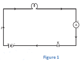
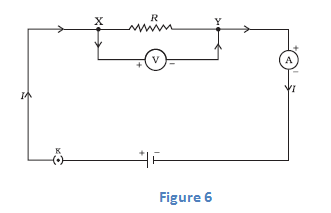
A continuous and closed path of an electric current is called an electric circuit. For example figure given below shows a typical electric circuit comprising a cell, an electric bulb, an ammeter A and a plug key K.
Note that the electric current flows in the circuit from the positive terminal of the cell to the negative terminal of the cell through the bulb and ammeter
The conventional direction of electric current is from positive terminal of the cell to the negative terminal through the outer circuit.
Or we can say that conventional direction of electric current is in the direction of the flow of positive charged carriers.
Electric Current Concept Map
6. Circuit Diagrams
We already know that electric circuit is a continuous path consisting of cell (or a battery), a plug key, electrical component(s), and connecting wires.
Electric circuits can be represented conveniently through a circuit diagram.
A diagram which indicates how different components in a circuit have to be connected by using symbols for different electric components is called a circuit diagram.
Table given below shows symbols used to represent some of the most commonly used electrical components
Ohm's Law
Ohm's law is the relation between the potential difference applied to the ends of the conductor and current flowing through the conductor. This law was expressed by George Simon Ohm in 1826.
Statement of Ohm's Law If the physical state of the conductor (Temperature and mechanical strain etc.) remains unchanged, then current flowing through a conductor is always directly proportional to the potential difference across the two ends of the conductor
mathematically
V ∝ I
or
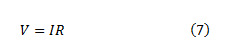
V=IR
where constant of proportionality R is called the electric resistance or simply resistance of the conductor.
Value of resistance depends upon the nature, dimension and physically dimensions of the conductor.
From Ohm's Law
Thus electric resistance is the ratio of potential difference across the two ends of conductor and amount of current flowing through the conductor.
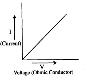
If a graph is drawn between the potential difference readings (V) and the corresponding current value (I), then the graph is found to be a straight line passing through the origin as shown below in the figure
From graph we see that these two quantities V and I are directly proportional to one another.
Also from this graph we see that current (I) increases with the potential difference (V) but their ratio V/I remain constant and this constant quantity as we have defined earlier is called the Resistance of the conductor.
Electric resistance of a conductor is the obstruction offered by the conductor to the flow of the current through it.
SI unit of resistance is Ohm (Ω) where 1 Ohm=1 volt/1 Ampere or 1Ω=1VA-1. Bigger units of resistance are Kilo-Ohm and Mega-Ohm
$1K\Omega = {10^3}\Omega $
$1M\Omega = {10^6}\Omega $
The resistance of the conductor depends
on its length,
on its area of cross-section
on the nature of its material
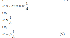
Resistance of a uniform metallic conductor is directly proportional to its length (l) and inversely proportional to the area of cross-section (A). That is, Where ρ is the constant of proportionality and is called the electrical resistivity of the material of the conductor.
The SI unit of resistivity is Ω m. It is a characteristic property of the material.
The metals and alloys have very low resistivity in the range of 10-8 Ω m to 10-6 Ω m. They are good conductors of electricity.
Insulators like rubber and glass have resistivity of the order of 1012 to 1017 Ω m.
Both the resistance and resistivity of a material vary with temperature.
Ohmic and Non-Ohmic resistors (or devices)
From above figure 2 we can see that straight line graph means that ratio V/I is constant . This constant ratio is called resistance R of the conductor. Resistance may be ohmic or non-ohmic.
(a) Resistors (or devices) for which potential difference and current graph is a straight line are called ohmic resistors. Their resistance remains same throughout their operation.
Examples are metallic conductors.
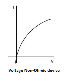
(b) Resistors (or devices) for which potential difference-current graph is not a straight line are called non-ohmic resistors.
Examples are liquid electrolytes, diodes etc.
Concept Map of Ohm's Law
Solved Questions on Ohm's Law Class 10
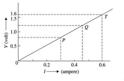
Question 1. What causes resistance in a conductor? Answer. When electrons move from one end of the conductor to the other end , then because of the potential difference they collide with the electrons, atoms and ions present in the conductor. Due to these collisions movement of the electrons gets restricted through the conductor. Thus “resistance is the property of the conductor due to which it opposes the flow of charge”. Solved Example 1. Following graph was plotted between V and I values.
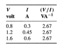
What would be the values of VI/ ratios when the potential difference is 0.8V, 1.2V and 1.6V respectively? What conclusion do you draw from these values? Solution
Hint: Choose convenient scales for X-axis and Y-axis (X-axis, 1 cm= 0.1 A, Y-axis, 1 cm= 0.5 V) and mark the current bid potential difference values as shown. Draw horizontal lines corresponding to the potential difference values of 0.8V, 1.2V and 1.6V; which meet the graph at P. Q and T respectively. From P. Q and T draw vertical lines to the X-axis and get the respective current values. Tabulate as given below and find the values of V/I
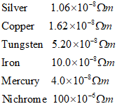
From the nature of the graph (which is a straight line) and above table we can conclude that  is same at every point. We find that V/I is same and found to be a constant. The wire obeys ohm's law and its resistance R = 2.67 ohm. Solved Example 2. Electrical resistivity's of some substances at 20°C are given below:
Answer the following questions using above data:
(a) Among silver and copper, which one is a better conductor? Why?
(b) Which material would you advise to be used in electrical heating devices and why? Answer. (a) Silver is better conductor as its resistivity is less then that of copper.
(b) Nichrome, as it has a greater value of resistivity as compared to the others. Solved Example 3. A simple electric circuit has 24 V battery and a resistor of 60 ohm. What will be the current in the circuit. The resistance of the connecting wire is negligible. Solution. Here Voltage (potential difference)=24 V
Circuit resistance , R= 60 Ohm
Current I=? To be calculated
From Ohm’s Law
$R = \frac{V}{I}$
Or we have
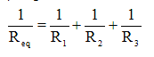
$I = \frac{V}{R}$
Putting the values we get
$I = \frac{{24V}}{{60\Omega }} = 0.4A$
The current in the circuit will be 0.4A.
8. Factors affecting of resistances of a conductor
Electric resistance of a conductor (or a wire) depends on the following factors
Length of the conductor: -
From equation 5 we can see that resistance of a conductor is directly proportional to its length. So, when length of the wire is doubled, its resistance also gets doubled; and if length of the wire is halved its resistance also gets halved.
Thus a long wire has more resistance then a short wire.
Area of cross-section:-
Again form equation 5 we see that resistance of a conductor is inversely proportional to its area of cross-section. So, when the area of cross-section of a wire is doubled, its resistance gets halved; and if the area of cross-section of wire is halved then its resistance will get doubled.
Thus a thick wire has less resistance and a thin wire has more resistance.
3. Nature of material of conductor:-
Electrical resistance of a conductor also depends on the nature of the material of which it is made. For example a copper wire has less resistance then a nichrome wire of same length and area of cross-section.
4. Effect of temperature:-
It has been found that the resistance of all pure metals increases on raising the temperature and decreases on lowering the temperature.
Resistance of alloys like manganin, nichrome and constantan remains unaffected by temperature.
9. Resistance of a system of resistors
We know that current through a conductor depends upon its resistance and potential difference across its ends.
In various electrical instruments resistors are often used in various combinations and Ohm’s Law can be applied to combination of resistors to find the equivalent resistance of the combination.
The resistances can be combined in two ways
In series
In parallel
To increase the resistance individual resistances are connected in series combination and to decrease the resistance individual resistances are connected in parallel combination.
9(a) Resistors in Series
When two or more resistances are connected end to end then they are said to be connected in series combination.
Figure below shows a circuit diagram where two resistors are connected in series combination.
Now value of current in the ammeter is the same irrespective of its position in the circuit. So we conclude that " For a series combination of resistors the current is same in every part of the circuit or same current flows through each resistor "
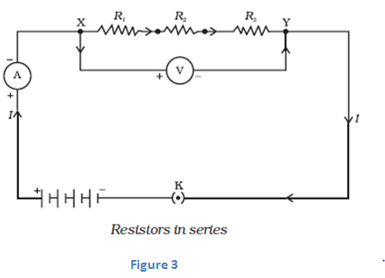
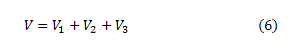
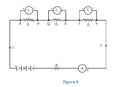
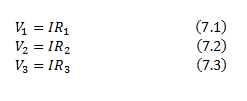
Again if we connect three voltmeters one across each resistor as shown below in the figure 4.The potential difference measured by voltmeter across each one of resistors R1 , R2 and R3 is V1 , V2 and V3 respectively and if we add all these potential differences then we get
This total potential difference V in equation 6 is measured to be equal to potential difference measured across points X and Y that is across all the three resistors in figure 3. So, we conclude that <"the total potential difference across a combination of resistors in series is equal to the sum of potential differences across the individual resistors."
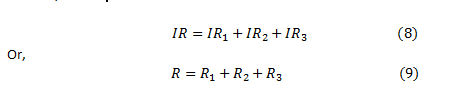
Again consider figure 4 where I is the current flowing through the circuit which is also the current through each resistor. If we replace three resistors joined in series by an equivalent single resistor of resistance R such that, the potential difference V across it, and the current I through the circuit remains same.
Now applying Ohm’s law to entire circuit we get<
On applying Ohm's law to the three resistors separately we have,< From equation 6 So here from above equation 9 we conclude that when several resistances are connected in series combination, the equivalent resistance equals the sum of their individual resistances and is thus greater than any individual resistance.
9(b) Resistors in parallel
When two or more resistances are connected between the same two points they are said to be connected in parallel combination.
Figure below shows a circuit diagram where two resistors are connected in parallel combination.
IMPORTANT NOTE
When a number of resistors are connected in parallel, then the potential difference across each resistance is equal to the voltage of the battery applied.
When a number of resistances are connected in parallel, then the sum of the currents flowing through all the resistances is equal to total current flowing in the circuit.
When numbers of resistances are connected in parallel then their combined resistance is less than the smallest individual resistance. This happens because the same current gets additional paths to flow resulting decrease in overall resistance of the circuit
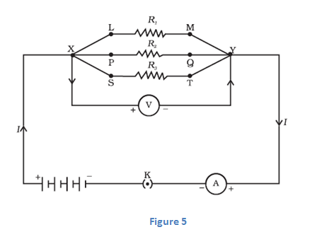
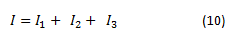
To calculate the equivalent resistance of the circuit shown in figure 5 consider a battery B which is connected across parallel combination of resistors so as to maintain potential difference V across each resistor. Then total current in the circuit would be
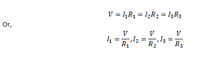
Since potential difference across each resistors is V. Therefore, on applying Ohm's Law
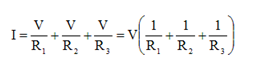
Putting these values of current in equation 10 we have
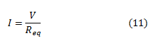
If R is the equivalent resistance of parallel combination of three resistors heaving resistances R1, R2 and R3 then from Ohm's Law Or, Comparing equation (10) and (11) we get
For resistors connected in parallel combination reciprocal of equivalent resistance is equal to the sum of reciprocal of individual resistances.
Value of equivalent resistances for capacitors connected in parallel combination is always less than the value of the smallest resistance in circuit.
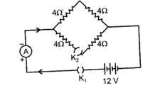
Question Calculate the electric current in the given circuit when
(a) Key K1 is open and K2 is closed
(b) both keys are closed
(c) Key K2 is open and K1 is closed
Solution .
(a) When, key K1 is open and K2 is closed , then no current flows in the circuit as circuit is an open circuit.
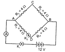
(b) When both keys are closed a current begin to flow in the circuit. Let us consider the circuit given below where we have labelled above given circuit.
How to determine equivalent resistance:-
(i) Now if you look closely at the circuit you would find that current is dividing at point A and combining again at point B.
(ii) Same amount of current (say I1) will flow through resistors R1 and R2 also same amount of current (say I2) will flow through resistors R3 and R4.
(iii)We are aware of the fact that “For a series combination of resistors the current is same in every part of the circuit or same current flows through each resistor”. So we can say that resistors R1 and R2 are connected in series combination. Similarly resistors R3 and R4 are also connected in series combination.
(iv) again as mentioned above in step (i) current is dividing at point A so we have different currents flowing through the combination of resistors R1 and R2 and resistors R3 and R4.
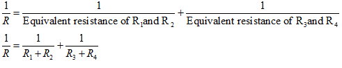
(v)So equivalent resistance of resistors R1 and R2 which is (R1 + R2) and equivalent resistance of resistors R3 and R4 which is (R3 + R4) are connected in parallel combination to each other as they have different amount of current flowing through them.
(vi)So, Equivalent resistance in the circuit would be
Putting the values as given in the question we get
(c) When key K2 is open and K1 is closed, the part ADB will become an open circuit, So no current will flow in this part of the circuit.
Therefore, net resistance of the circuit will be
$R = {R_1} + {R_2} = 4 + 4 = 8\Omega $
Therefore, electric current.
$I = \frac{V}{R} = \frac{{12}}{8} = 1.5A$
Watch this tutorial for learning about how to solve resistance problems for class 10.
10. Heating Effect of Electric current
When electric current passes through a high resistance wire, the wire becomes and produces heat. This is called heating effect of current.
This phenomenon occurs because electrical energy is gets transformed into heat energy when current flows through a wire of some resistance say R Ω.
Role of resistance in electrical circuits is similar to the role of friction in mechanics.
To we will now derive the expression of heat produced when electric current flows through a wire.
To we will now derive the expression of heat produced when electric current flows through a wire.
For this consider a current I flowing through a resistor of resistance R. Let V be the potential difference across it as shown in the figure 6
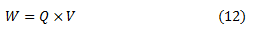
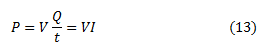
Let t be the time during which charge Q flows. Now when charge Q moves against the potential difference V , then the amount of work is given by Therefore the source must supply energy equal to VQ in time t. Hence power input to the circuit by the source is
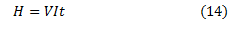
The energy supplied to the circuit by the source in time t is P×t that is, VIt. This is the amount of energy dissipated in the resistor as heat energy.
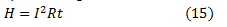
Thus for a steady current I flowing in the circuit for time t , the heat produced is given by Applying Ohm's law to above equation we get This is known as Joule's Law of heating
According to Joule's Law of Heating , Heat produced in a resistor is
(a) Directly proportional to the square of current for a given resistor.
(b) Directly proportional to resistance of a given resistor.
(c) Directly proportional to time for which current flows through the resistor.
11. Applications of heating effect of current
The heating effect of current is utilized in the electrical heating appliances for example electric iron, room heaters, water heaters etc.
The heating effect of electric current is utilized in electric bulbs or electric lamps for producing light.
An electric fuse is an important application of the heating effect of current. The working principle of a fuse wire is based on the heating effect of current. When high current flow through the fuse (current higher than the rated value) then the heat developed in the wire melts it and breaks the circuit.
In an electric heater one type of coil is used. A high resistance material like nichrome or same type of material is used as coil. The coil is wound in grooves on ceramic format or china clay. Flowing electric current through the coil it becomes heated. Due to high resistance the coil becomes red color forms.
12. Electric Power
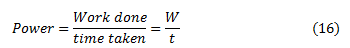
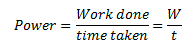
Rate of doing work or the rate of consumption of energy is known as POWER
Mathematically,
SI unit of power is Watt which is denoted by letter W. The power of 1 Watt is a rate of working of 1 Joule per second.
Actually Watt is a small unit, therefore , a bigger unit of electric power called Kilowatt is used for commercial purposes. Also ,
1 kilowatt = 1000 Watts So,
" the rate at which electric work is done or the rate at which electric energy is consumed is called electric power "
We will now derive formula for the calculation of electric power.
From equation 14 we know that
Now we know that work done W by current I when it flows for time t under a potential difference V is given by
Putting this value of work done in equation 16 we get
Hence,
Electric Power = voltage x current
12 (a) Power in terms of I and R
From equation 17 we know that
$P=VI$
Now from Ohm's law
Putting above equation in equation 15 we get
$P=I \times R \times I$
Power , $P=I^2 \times R$
Above formula is used to calculate power when only current and resistance are known to us.
12 (b) Power in terms of V and R
From equation 17 we know that P=VI
Now from Ohm's law Or we have
Putting this value of I in equation 15 we get
$P = V \times \frac{V}{R}$
$P = \frac{V^2}{R}$
This formula is used for calculating power when voltage V and resistance R is known to us.
It is clear from the above equation that power is inversely proportional to the the resistance.
Thus the resistance of high power devices is smaller then the low power ones.
For example , the resistance of a 100 Watt bulb (220 V) is smaller then that of 60 Watt (220 V) bulb.
We have three formulas for calculating electric power. These are
(1) $P = V \times I$
(2) $P= I^2 \times R$
(3)$P = \frac{V^2}{R}$
You must memorize these formulas as they would be used to solve numerical problems.
When electrical appliance consumes electrical energy at the rate of 1 Joule per second , its power is said to be 1 Watt.
Rate at which electric work is done or the rate at which electric energy is consumed , is called electrical power.