It is a common observation with the waves of all kind that they bend round the edge of an obstacle
Light like other waves also bends round corners but in comparison to sound waves small bending of light is due to very short wavelength of light which is of the order of 10-5
This effect of bending of beams round the corner was first discovered by grimed (Italy 1618-1663)
We now define diffraction of light as the phenomenon of bending of light waves around the corners and their spreading into the geometrical shadows
Fresnel then explained that the diffraction phenomenon was the result of mutual interference between the secondary wavelets from the same dif wave front
Thus we can explain diffraction phenomenon using Huygens�s principle
The diffraction phenomenon are usually divided into two classes
i) Fresnel class of diffraction phenomenon where the source of light and screen are in general at a finite distance from the diffracting aperture
ii) Fruanhofer class of diffraction phenomenon where the source and the screen are at infinite distance from the aperture, this is easily achieved by placing the source on the focal plane of a convex lens and placing screen on focal plane of another convex lens. This class of diffraction is simple to treat and easy to observe in practice
Here in this chapter we will only be considering fraunhofer class diffraction by a single slit
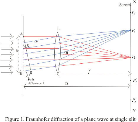
2. Fraunhofer Diffraction by single slit
Let us first consider a parallel beam of light incident normally on a slit AB of width 'a' which is of order of the wavelength of light as shown below in the figure
A real image of diffraction pattern is formed on the screen with the help of converging lens placed in the path of the diffracted beam
All the rays that starts from slit AB in the same phase reinforce each other and produce brightness at point O on the axis of slit as they arrive there in the same phase
The intensity of diffracted beam will be different in different directions and there are some directories where there is no light
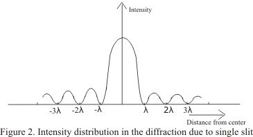
Thus diffraction pattern on screen consists of a central bright band and alternate dark and bright bands of decreasing intensity on both sides
Now consider a plane wave front PQ incident on the narrow slit AB. According to Huygens principle each point t on unblocked portion of wavefront PQ sends out secondary wavelets in all directions
Their combined effect at any distant point can be found y summing the numerous waves arriving there from the principle of superposition
Let C be the center of the slit AB.The secondary waves, from points equidistant from center C of the slit lying on portion CA and CB of wave front travel the same distance in reaching O and hence the path difference between them is zero
These waves reinforce each other and give rise to the central maximum at point O
i) Condition for minima
We now consider the intensity at point P1 above O on the screen where another set of rays diffracted at a angle θ have been bought to focus by the lens and contributions from different elements of the slits do not arise in phase at P1
If we drop a perpendicular from point A to the diffracted ray from B,then AE as shown in figure constitutes the diffracted wavefront and BE is the path difference between the rays from the two edges A and B of the slit.
Let us imagine this path difference to be equal to one wavelength.
The wavelets from different parts of the slit do not reach point P1 in the phase because they cover unequal distance in reaching P1.Thus they would interfere and cancel out each other effect. For this to occur
BE=λ
Since BE=ABsinθ
asinθ=λ
or sinθ=λ/a
or θ=λ/a ---(1)
As angle of diffraction is usually very small so that
sinθ=θ
Such a point on screen as given by the equation (1) would be point of secondary minimum
It is because we have assume the slit to be divided into two parts, then wavelets from the corresponding points of the two halves of the slit will have path difference of #955;/2 and wavelets from two halves will reach point P1 on the screen in a opposite phase to produce minima
Again consider the point P2 in the figure 1 and if for this point path difference BE=2λ ,then we can imagine slit to be divided into four equal parts
The wavelets from the corresponding points of the two adjacent parts of the slit will have a path difference of λ/2 and will mutually interfere to cancel out each other
Thus a second minimum occurs at P2 in direction of θ given by
θ=2θ/a
Similarly nth minimum at point Pn occurs in direction of θ given by
θn=nθ/a ---(2)
ii) Positions of maxima
If there is any point on the screen for which path difference
BN=asinθ=3θ/2
Then point will be position of first secondary maxima
Here we imagine unblocked wavefront to be divided into three equal parts where the wavelets from the first two parts reach point P in opposite phase thereby cancelling the e effects of each other
The secondary waves from third part remain uncancelled and produce first maximum at the given point
we will get second secondary maximum for BN=5θ/2 and nth secondary maxima for
BN=(2n+1)θ/2 =asinθn ---(3)
where n=1,2,3,4..
Intensity of these secondary maxima is much less then central maxima and falls off rapidly as move outwards
Figure below shows the variation of the intensity distribution with their distance from the center of the central maxima