What is a Series Circuit?
Electricity is one of the purest and the most efficient forms of energy humans have ever produced. Mankind has also fabricated ways to use this energy to perform all kinds of work using the intermediate medium of circuits. As we know, these circuits are hugely classified into 2 types of combinations known as the ‘Parallel’ and ‘Series’ combination.
In this article, we are going to see the working of series combinations of various electrical components in a circuit. Here we will discuss the series combination of components like
- Resistors
- Capacitors and
- Inductors
Series Circuits Definition
In ‘Electrical Engineering’ series circuits mean that the components used in the circuit are present in a series combination. But what does it mean when the components are present in a series combination…? Well, this can be understood further with the following figure and the statements accompanying with it,
Characteristics of Series Circuit
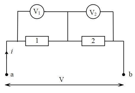
- In series combination, the electrical components are joined in such a way where the negative terminal of a component is connected to the positive terminal of its succeeding component and so on.
- In series combination, an equal magnitude of current passes through all the components present in the series combination no matter what.
- The charges in this circuit will pass such that every charge will pass through each component that is connected in the series combination. This phenomenon is totally opposite to what happens in the parallel combination.
- The potential difference across each electrical component in the series combination will be different and will depend upon the resistance properties that the component possesses.
- The current through ‘a’ will go undisturbed through both the electrical components which are in series and therefore each component will receive the same current. (Refer to Figure 1.)
We got to know what are series circuits and the set of rules that define it and with this, we will go further to discuss the series combinations in ‘Resistors’, ‘Capacitors’, and ‘Inductors’.
Examples of series Circuits
Let us now look at series combination of some electrical components one by one.
Series Combination of Resistors:
Formula to remember: $V = IR$

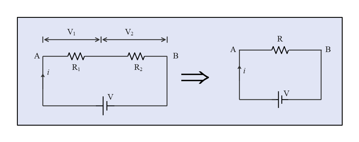
In the figure above, the two resistors with resistances $R_1$ and $R_2$ are connected in series. The voltage across each of them is $V_1$ and $V_2$ respectively and the current flowing through both of them is given by $i$.
Here,
$V=V_1+V_2$
Let R be the equivalent resistance which can be assumed from the right-hand side figure.
From the formula, we have
$V = iR$,
$V_1=iR_1$
and
$V_2=iR_2$
From the above two equations we can find the relation for equivalent resistance which is,
$iR=i(R_1+R_2)$
$R = R_1+R_2$
Therefore, for ‘n’ resistors connected in parallel, the equivalent resistance would be,
$R = R_1+R_2 + R_3+………..+R_n$
Series Combination of Capacitors
Formula to remember: $q = CV$
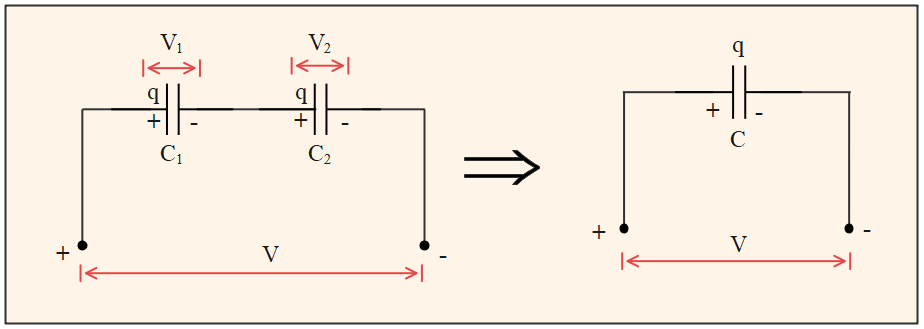
The above figure shows two capacitors with capacitance $C_1$ and $C_2$ in series combination. The voltage across each of them is $V_1$ and $V_2$ respectively. In series combination, the magnitude of the charge on all capacitor plates is the same (here $q$). So,
$\frac{V_1}{V_2}= \frac{C_2}{C_1}$
Let the equivalent capacitance be represented by $C$ with the total charge $q$ on it.
We know that,
$V = V_1 + V_2$
$\frac{q}{C} = \frac{q}{C_1} + \frac{q}{C_2}$
With this the equivalent resistance will be,
$\frac{1}{C} = \frac{1}{C_1} + \frac{1}{C_2}$
Therefore, for ‘n’ capacitors connected in series, the equivalent resistance would be,
$\frac{1}{C} = \frac{1}{C_1} + \frac{1}{C_2}+ \frac{1}{C_3}+…………++ \frac{1}{C_n}$
Series Combination of Inductors
Formula to remember: $V = L\frac{di}{dt}$
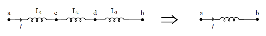
The above figure depicts the series combination of inductors that have inductances of magnitude $L_1$,$ L_2$, and $L_3$ respectively. The current passing through all inductors is $i$ The voltage across each inductor can be given as,
$V_a – V_c = L_1\frac{di}{dt}$
$V_c – V_d = L_2\frac{di}{dt}$
$V_d – V_b = L_3\frac{di}{dt}$
Adding all the equations above, we get
$V_a – V_b = (L_1 + L_2 + L_3)\frac{di}{dt}$
The figure on the right-hand side shows the equivalent inductance as ‘L’.
Therefore,
$V_a – V_b = L\frac{di}{dt}$
From the following equations, we can derive that,
$L = L_1 + L_2 + L_3$
Therefore, for ‘n’ inductors connected in parallel, the equivalent inductance would be,
$L = L_1 + L_2 + L_3+ … + L_n$
Applications of Series circuits
Series circuits also have an equal importance as the parallel circuits in electrical engineering and applications. Some of the applications are given below:
Runway Lights at Airport
Airport runways display a beautiful view of series of lights which are actually based upon the principle of series combination. These beautiful lights you notice out of your flight’s window are actually for guiding the pilots to the runway with ease. These lights which are large in number are powered by a small gauge wire over a great distance. Each light has a small current transformer that supplies a proper voltage and current. If a bulb burns out, the small transformer just saturates and completes the circuit which helps to keep the remaining lights working.
Electric Fuse
Electric fuse has a huge importance in terms of safety and its working principle consists a series connection with the further circuit (e.g. ‘a building’) and ‘heating effect of current’. So when a higher magnitude passes through this fuse the filament will automatically melt due to the heat generated by the excess current. This melting phenomenon results in a broken circuit and stops the current supply to various appliances further ultimately saving them from this fluctuation.
Voltage Divider Circuits
Series circuits are useful in applications where voltage divider circuits are required. Resistors in series combination produce a voltage divider circuit. For example, voltage dividers are used for measuring the resistance of a sensor. To create such a circuit, the sensor is connected in series with a known resistance and a known voltage is applied across the divider. A potentiometer is yet another example which is used as a variable voltage divider in volume control of radios.
Related Articles
- Combination of Capacitors
- What is inductance?
- Combination of resistors
- http://hyperphysics.phy-astr.gsu.edu/hbase/electric/conins.html#c3