Voltmeter when connected across any circuit element should not draw any current from it. If the voltmeter resistance is not high as compared to the resistance of the circuit element, across which it is connected, the measured voltage becomes less. Thus resistance of the voltmeter should be as large as possible.
Answer
Hence (c) is the correct answer
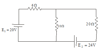
(i) Consider the circuit given in the question
Answer(2-4)
Rate at which energy is dissipated in 20 Ω is
P=I2R
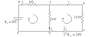
So we need to calculate the current through 20 Ω resistor. Applying Kirchoff’s loop rule in ABCDA we get equation
E1 -6I1 +10 I2 =0
or
20 -6I1 +10 I2 =0 ----(1)
Applying Kirchoff’s loop rule in CDEFC we get equation
E2 -10I2 -20I3 =0
24- 10I2 -20I3 =0 ---(2)
From Kirchoff’s junction rule at point C
I1 + I2 = I3
putting this in equation 2 we find
24-30I2 -20I1 =0 -----(3)
Solving equation 1 and 3 for the value of I1 we get
I1=2.21A
Again from equation 1 we find
I2=-0.67A here consider reversing the direction of current from the assumed one.
And finally
I3=1.54A
Rate at which energy is dissipated in 20 Ω is
P=I2R=(1.54)2x20=47.2 Watt
Hence (d) is the correct answer
(ii) I2 is the current through 10Ω resistor
Hence (b) is the correct answer
(iii) Power of battery is
Pemf=iE
Power supplied by battery E1 = I1E1=44.2 Watt
Hence (a) the correct answer
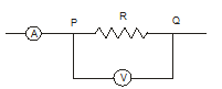
Applying Ohm’s law in section PQ
Answer
V=IR
The resistances, R and internal resistance of the voltmeter are connected in parallel
$\frac {I}{V} =\frac {1}{R} + \frac {1}{R_v}$
or
$\frac {1}{R} = \frac {I}{V} - \frac {1}{R_v} = \frac {R_v I -V}{VR_v}$
Thus
$R=\frac {V}{I - \frac {V}{R_v}}$
putting the respective values and calculating we find R=20.13Ω
Hence (c) the correct answer
$H=\frac {V^2 t}{R}$
Answer
but
$R=\frac {\rho L}{A} =\frac {\rho L}{\pi r^2}$
Hence
$H=\frac {V^2 t r^2 \pi}{\rho L}
Hence (b) the correct answer
Rate at which heat is produced in the wire is
Answer
$\frac {heat}{time} =\frac {V^2}{R} = 2205 Js^-1$
Latent heat of ice=80c/gm=80x4.2J/gm
Hence rate of melting ice would be =$\frac {2205}{80X4.2} =6.56g/s$
Hence (c) the correct answer
(d) is the correct answer
Answer

When radius of the wire is changed , it will not affect the ratio of resistance of two arms AC and BC of the slide wire bridge.
Answer
Hence (d) is the correct answer
10 (b)
Answer
11.(d)
12 (a)
13 (a)
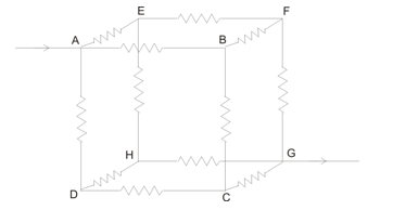
Given that current I enter the cube at point A and leaves at point G as shown below in the figure
Answer
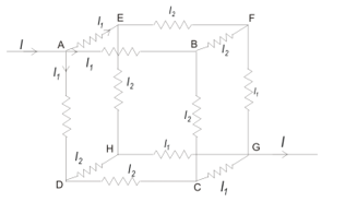
Here we have
I1=2I2
And also from point rule we have I=3I1
If E is the emf connected across the system then
E=IReq
Applying Kirchhoff’s law to any path between A and G , say ABFG , we get
I1R+I2R+I1R=V=IReq
Putting I1=2I2 in above equation we get
5I2R=IReq
Since I=3I1 so we have I=6I2
From this we have
5I2R=6I2Req
Or, Req=5R/6
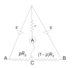
Let I be the amount of current through the ammeter, I1 be the current due to left hand EMF and $I_2$ be the current due to right hand emf. Applying Kirchhoff's law we find
Answer
$E-Ir-I_1pR_0=0$
$E-Ir-I_2(1-p)R_0=0$
and
$I=I_1+I_2$
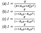
Solving for I we get
$I=\frac{E}{\left(r+R_0p-R_0p^2\right)} $
For maximum I denominator should be smallest which is for two values of p i.e., for p=0,1.
Answer
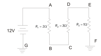
From the figure in the question we see that all the resistors are connected in the series combination. So equivalent resistance of the circuit is
Answer
$R=R_1+R_2+R_3 = 6$ ω
Total current in the circuit is I=V/R = 12/6 =2A
Answer
For finding potential difference between points A and E we first need to find the effective resistance between these two points.
Answer
$R_{AE} = 2+3=5$ ω
$V_{AE} = IR_{AE} = 10$ V
$V_E$ is the voltage across the resistor $R_3$ . So,
Answer
$V_E=R_3I = +2$ V above the ground
Power supplied is P=VI = 24W
Answer
|
Column A |
Column B |
|
(P) Point of lowest potential in circuit A has its value equal to |
(U) 0.15 A |
|
(Q) Circuit current in circuit B is |
(V) 4V |
|
(R) Circuit current in circuit A is |
(W) 15V |
|
(S) Potential of point B in circuit B is |
(X) 90V |
|
(T) Potential at point B in circuit A is |
(Y) .5A |
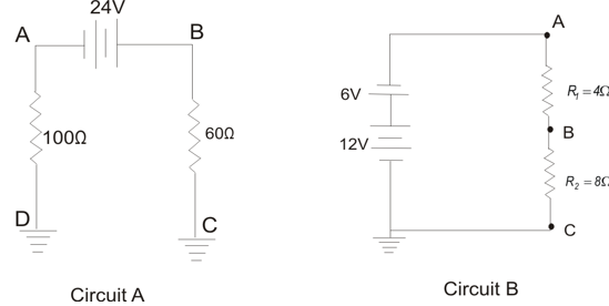
First consider circuit A for finding value of lowest potential. Point of lower potential in circuit A is the point of maximum negative potential and its value is
Answer
V=IR
Where
I= 24/160 = .15 A is the current in the circuit.
So,
Lowest potential is
V=-0.15 × 100 = -15 V
That is 15 V below the ground.
Now potential at point B in circuit A = 0.15 × 60 =+9V
Now we find circuit current in circuit B
Net voltage= 12-6 = 6V
Total resistance in the circuit = 4+8 = 12 ω
And circuit current is, I =6/12 = .5A
Now potential at point B in circuit B = $V_A-(4 \times 0.5)$
Again potential at point A in circuit B =12-6=+6V which is positive w.r.t. ground
$V_B = 6-2= +4V$
P -> W ; Q -> Y ; R - >U ; S ->V ; T- >X
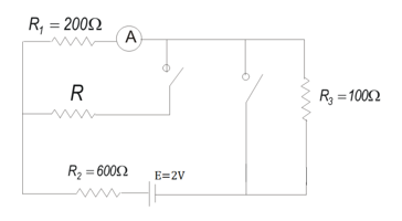
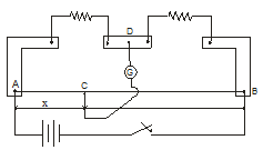
When both the switches are open resistances $R_1$, $R_2$ and $R_3$ are in series combination,So current through ammeter would be
Answer
$I_A= \frac {E}{R_1 + R_2 + R_3}$
Again with both Switches closed
Voltage at points a and b would be same and no current passes through resistance $R_3$. Now current through E and $R_2$
$I'=\frac {E}{R_2 + \frac {RR_1}{R_1 + R}}$
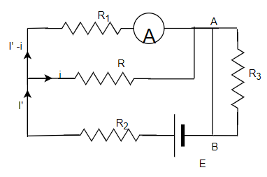
Current through Ammeter would be the current through resistor $R_1$. If i is current through resistor R then I' -i would be the current through $R_1$ and ammeter. So from Kirchoff's law
$(I' -i)R_1 = iR$
or
$i= \frac {I' R_1}{R+ R_1}$
So current through ammeter
$=I' -i = I' - \frac {I' R_1}{R+ R_1}= \frac {I'R}{R+R_1}$
or
$=\frac {RE}{(R+R_1)R_2 + RR_1}$
Now since Ammeter reports same reading before and after
$\frac {RE}{(R+R_1)R_2 + RR_1}=\frac {E}{R_1 + R_2 + R_3}$
$R(R_1 + R_2 + R_3)=(R+R_1)R_2 + RR_1$
$RR_1 + RR_2 + RR_3 = RR_2 + R_1 R_2 + RR_1$
or
$R= \frac {R_1}{R_2}{R_3} = \frac {200 \times 600}{100} = 1200$ ω

In charging of a capacitor we have
Answer
$q=q_0(1-e^{-\frac{t}{RC}})$ --- (1)
Where $q_0 = CV$
(a) $q_0=CV=\left(20\times{10}^{-6}F\right)\left(6V\right)=\ 120\mu C$
(b) Time constant is given by
$\tau=RC=\left(200\Omega\right)\left(20\times{10}^{-6}F\right)=4\times{10}^{-3}s$.
Now from equation 1 if charge reaches ${\frac{1}{2}q_0}$ in time t then
$ e^{-\frac{t}{RC}}=\frac{1}{2}$
Taking log on both the sides and solving for t we get
$t=t_{1/2}=2.8 \times 10^{-3} $ s
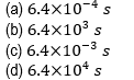
(c) $-\frac{t}{\tau}=ln 0.2$
or, $\ t=\tau\times1.6=4\times{10}^{-3}\times1.6=6.4\times{10}^{-3}\ $s
 Match the columns given below
|
Column A |
Column B |
|
(P) When switch S2 is open and S1 is closed and then opened after C1 , C2 and C3 are fully charged. Electric potential difference across each capacitor is |
(W) 0 V |
|
(Q) Now after opening S1 if switch S2 is closed, the electric potential difference across each capacitor is |
(X) V1=V3=36V , V2=V4=18V |
|
(R) In another case if switch S1 is open and switch S2 is first closed then electric potential difference across each capacitor is |
(Y) V=30 V |
|
(S) Now if switch S1 is closed , the potential difference across each capacitor is |
(z) V1=V3=30V , V2=V4=15V |
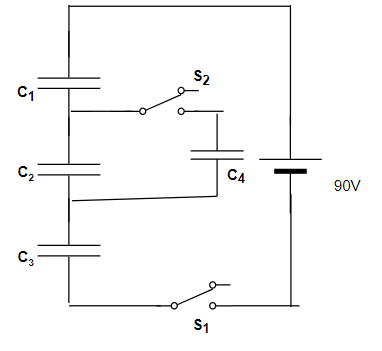
First when switch $S_2$ is open and $S_1$ is closed the capacitor $C_4$ is not included in the circuit and the effective circuit is shown below in the figure.
Answer
If battery provides a voltage of 90V then $V_1+V_2+V_3=V$ where $V_1$, $V_2$, and $V_3$ are voltages across the capacitors $C_1$, $C_2$, $C_3$ respectively.
Since all the capacitors are in series combination so charge on all the capacitor plates is same say, Q. Also given that
$C_1=C_2=C_3=C=10 \mu F$
$Q=C_1V_1= C_2V_2= C_3V_3$
$V_1=V_2=V_3=V'$
which gives ,
$3V'=V$ or $V'=90/3 = 30$V
Once the capacitors are charged this way, the potential difference across each capacitor will remain the same even after opening the switch $S_1$.
If we now open switch $S_1$ then battery is excluded from the circuit after charging of the capacitors $C_1$, $C_2$ and $C_3$. Now closing switch $S_2$ will bring $C_4$ in the circuit and effective circuit would be
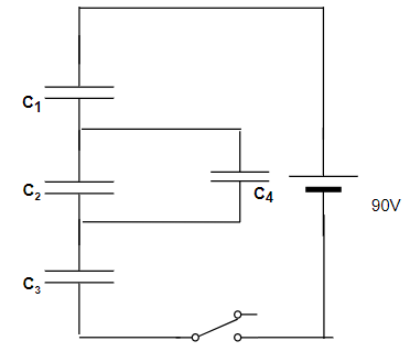
Capacitors $C_1$ and $C_3$ will still carry the same charge as before and opening of switch $S_1$ leaves them isolated from any flow of charge. Charge Q originally on capacitor $C_2$ is distributed between capacitor $C_2$ and $C_4$. As $C_2=C_4$ so charge on each capacitor equals Q/2 and voltage across $C_2$ and $C_4$ would be equal to half the original voltage across C2. Thus
$V_1=V_3=30V$ , $V_2=V_4=15V$
Again with capacitors initially uncharged and switch $S_1$ open , closing $S_2$ does not provide any potential difference across any capacitor as battery is effectively disconnected.
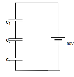
Now we close $S_1$ with $S_2$ closed previously and circuit arrangement is as shown below in the figure.
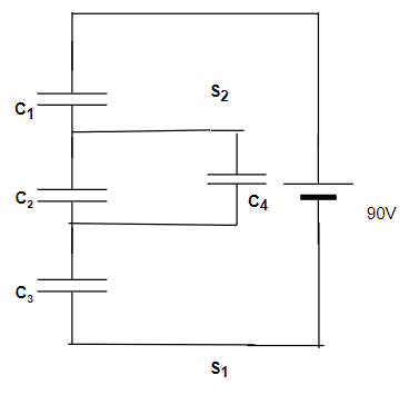
Effective capacitance of parallel combination between capacitors $C_2$ and $C_4$ is
$C_{24} = C+C = 2C$
And the entire system has equivalent capacitance
$\frac{1}{C_{eq}}=\left(\frac{1}{C_1}+\frac{1}{C_{24}}+\frac{1}{C_3}\right)$
Or,
$C_{eq}=\frac{2}{5}C$
Thus, charge drawn from the battery onto each of $C_1$, $C_24$ and $C_3$ is,
$Q'=C_{eq}V={\frac{2}{5}CV}$
$V_1=V_3=\frac{Q'}{C}=\frac{2}{5}CV=36V$
$V_2=V_4=\frac{Q'}{2C}=\frac{1}{5}CV=18V$
Hence P ->Y ; Q -> Z ; R -> W ; S ->X
(b), (d)
Answer