Class 10 Science Chapter 9 Light Reflection and Refraction Notes
In these light class 10 notes students learn about the reflection and refraction of light using the fact that light travels in straight line. These notes are for Class 10 Science Chapter 9 Light.
We hope you like these light reflection and refraction class 10 notes and if possible please shere these notes among your friends.
Introduction to Light
Light is a form of energy due to which we are able to see the objects which emits light for example objects like sun,
lamp, candle emits light of their own and thus they are known as luminous objects.
There are objects like table , chair etc. which are not luminous objects and still we are able to see them
and this happens because they reflects lights which falls on them from a luminous object like sun, lamp etc.
and when this reflected light reaches our eyes we are able to see such non luminous objects.
Light rays basically consist of electromagnetic waves which do not require any material medium
(like solid, liquid or gas) for their propagation.
Wavelength of visible light waves is very small and is of the order of \(4 \times {10^{-7}}m\) to \(8 \times {10^{ - 7}}m\).
Speed of light waves depends on the medium through which they pass as speed of light in air is slightly less than the speed of light in
vacuum \(8 \times {10^{ 8}}m/s \) same way speed of light in water and glass is much less than that in air.
When light falls on the surface of an object it can either be
Absorbed:- If an object absorbs all the light falling on it , then it will appear perfectly black for example a blackboard
Transmitted: - An object is said to transmit light if it allows light to pass through itself and such objects are transparent.
Reflected:- If an object sends back light rays falling on its surface then it is said to have reflected the light
Reflection of Light
The process of sending back light rays which falls on the surface of an object is called REFLECTION of light
Silver metal is one of the best reflectors of light.
Mirrors we use on our dressing tables in our home are plane mirrors.
A ray of light is the straight line along which the light traveled and a bundle of light rays is called a beam of light.
Laws of Reflection of light
The angle of incidence is equal to the angle of reflection, and
The incident ray, the reflected ray and the normal to the mirror at the point of incidence all lie in the same plane.
These laws of reflection are applicable to all types of reflecting surfaces including spherical surfaces
Real and Virtual images
An image is formed when the light rays coming from an object meet at a point after reflection from a mirror (or refraction from lens).
The images are of two types
Real Images:- Real images are formed when rays of light that comes from an object (or source) meets at a point after reflection from a mirror (or refraction from a lens). Real images can be formed on a screen and can be seen with the eyes.
Virtual images:- Virtual image is an image in which the outgoing rays from an object do not meet at a point. It will appear to meet at a point in or behind the optical device (i.e., a mirror) but they do not actually meet after reflection from a mirror (or refraction from a lens). A plane mirror always forms virtual images.
Characteristics of images formed by mirrors:-
(a) Images formed by mirrors are always virtual and erect
(b) Size of image is always equal to the size of the object and the image is laterally inverted.
(c) The images formed by the plane mirror are as far behind the mirror as the object in front of the mirror.
Lateral inversion:- If an object is placed in front of the mirror, then the right side of the object appears to be the left side and left side of the object appears to be the right side of this image. This change of sides of an object and its mirror image is called lateral inversion.
Spherical Mirrors
The reflecting surface of a spherical mirror may be curved inwards or outwards.
Spherical mirrors are of two types
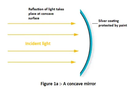
1. Concave mirror: - In a concave mirror reflection of light takes place at the concave surface or bent-in surface as shown below in the figure.
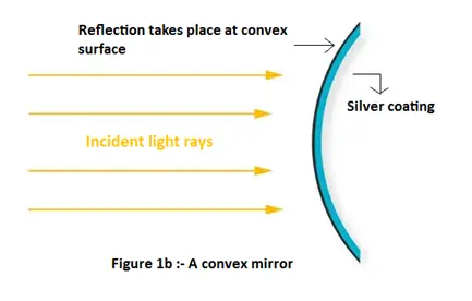
2. Convex mirror:- In a convex mirror reflection of light takes place at the convex surface or bent out surface as shown below in the figure
Commonly used terms about Spherical mirrors :-
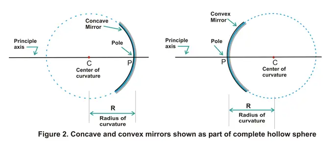
Center of curvature: - The reflecting surface of a spherical mirror forms a part of a sphere. This sphere has a center. This point is called the center of curvature of the spherical mirror. It is represented by the letter C. Please note that the center of curvature is not a part of the mirror. It lies outside its reflecting surface. The center of curvature of a concave mirror lies in front of it. However, it lies behind the mirror in case of a convex mirror as shown above in the figure 2.
Radius of curvature: - The radius of the sphere of which the reflecting surface of a spherical mirror forms a part, is called the radius of curvature of the mirror. It is represented by the letter R.
Pole: - The center of a spherical mirror is called its pole and is represented by letter P as can be seen in figure 2.
Principle axis: - Straight line passing through the pole and the center of curvature of a spherical mirror is called principle axis of the mirror.
Aperture of the mirror: - Portion of the mirror from which reflection of light actually takes place is called the aperture of the mirror. Aperture of the mirror actually represents the size of the mirror.
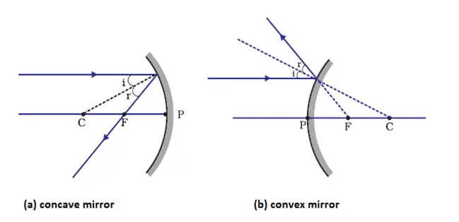
Principle focus and focal length of a Spherical Mirrors
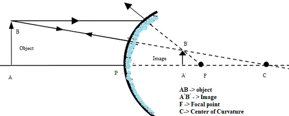
For understanding about principle focus and focus length of a spherical mirror first consider the figure given below
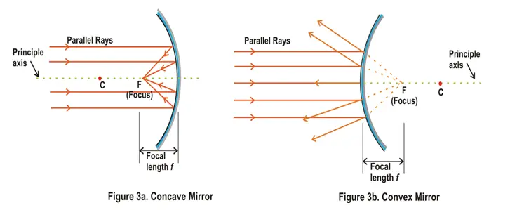
From figure 3a we see that a number of rays parallel to the principal axis are falling on a concave mirror. If we now observe the reflected rays we see that they are all intersecting at a point F on the principal axis of the mirror. This point is called the principal focus of the concave mirror.
In case of convex mirror rays get reflected at the reflecting surface of the mirror and these reflected rays appear to come from point F on the principle axis and this point F is called principle focus of convex mirror.
The distance between the pole and the principal focus of a spherical mirror is called the focal length. It is represented by the letter f.
There is a relationship between the radius of curvature R, and focal length f, of a spherical mirror and is given by R=2f which means that that the principal focus of a spherical mirror lies midway between the pole and centre of curvature.
Image Formation by Spherical mirrors
The nature, position and size of the image formed by a concave mirror depend on the position of the object in relation to points P, F and C.
The image formed can be real as well as virtual depending on the positions of the object.
The image is either magnified, reduced or has the same size, depending on the position of the object.
Rules for obtaining images formed by spherical mirrors
(1) Rule 1
A ray of light which is parallel to the principle axis of the mirror passes through its focus after reflection from the mirror as shown below in the figure
From the figure given above it can be clearly seen that the light rays passes through principle focus in case of concave mirrors and appears to diverge from principle focus in case of concave mirror.
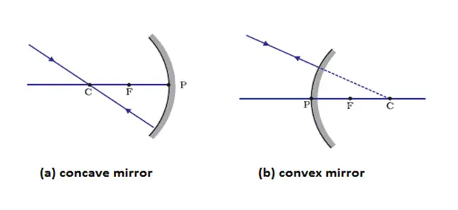
(2) Rule 2
A ray of light passing through the center of curvature of the curvature of the concave mirror or directed in the direction of the center of curvature of a convex mirror, is reflected back along the same path as shown below in the figure
This happens because the incident rays fall on the mirror along the normal to the reflecting surface.
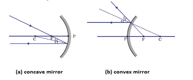
(3) Rule 3
A ray passing through principle focus of a concave mirror or a ray which is directed towards the principal focus of a convex mirror, becomes parallel to the principle axis after reflection and is shown below in the figure
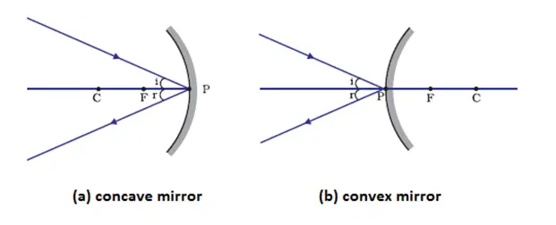
(4) Rule 4
A ray incident obliquely to the principal axis, towards a point P (pole of the mirror), on the concave mirror or a convex mirror, is reflected obliquely. The incident and reflected rays follow the laws of reflection at the point of incidence (point P), making equal angles with the principal axis and is shown below in the figure
Image formation by spherical mirrors
Image formation by concave mirror
The type of image formed by a concave mirror depends on the position of the object kept in front of the mirror.
We can place the object at following places
Between pole P and focus F
At the focus
Between focus F and center of curvature C
At the center of curvature
Beyond center of curvature
At far off distances called infinity and cannot be shown in the figures
Image formation by a concave mirror for different positions of the object is shown below in the table
Concave mirrors are used as shaving mirrors, reflectors in car headlights, hand torch and table lamps.
Large concave mirrors are used in field of solar energy to focus sun rays on objects to be heated.
Image formation by convex mirrors
In order to construct a ray diagram to find out the position, nature and size of image formed by convex mirror we should remember following path of rays of light.
A ray of light parallel to the principle axis of a convex mirror appears to be coming from its focus after reflection from the mirror.
A ray of light going towards the center of curvature of convex mirror is reflected back along its own path.
Convex mirrors have its focus and center of curvature behind it and no light can go behind the convex mirror and all the rays that we show behind the convex mirror are virtual and no ray actually passes through the focus and center of curvature of the convex mirror.
Whatever be the position of object in front of convex mirror, the image formed by a convex mirror is always behind the mirror, virtual, erect and smaller than the object.
Nature, position and relative size of the image formed by a convex mirror is given below in the table
Convex mirrors are used as rear view mirrors in automobiles to see the traffic at back side as they give erect images and also highly diminished one giving the wide field view of traffic behind.
Sign convention for reflection by spherical mirrors
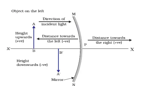
Reflection of light by spherical mirrors follow a set of sign conventions called the New Cartesian Sign Convention. In this convention, the pole (P) of the mirror is taken as the origin. The principal axis of the mirror is taken as the x-axis (X'X) of the coordinate system. The conventions are as follows -
The object is always placed to the left of the mirror. This implies that the light from the object falls on the mirror from the left-hand side.
All distances parallel to the principal axis are measured from the pole of the mirror.
All the distances measured to the right of the origin (along + x-axis) are taken as positive while those measured to the left of the origin (along - x-axis) are taken as negative.
Distances measured perpendicular to and above the principal axis (along + y-axis) are taken as positive.
Distances measured perpendicular to and below the principal axis (along -y-axis) are taken as negative.
These new Cartesian sign convention for spherical mirrors are shown below in the figure
Mirror formula and magnification
Mirror formula:-
It gives the relationship between image distance (v) , object distance (u) and the focal length (f) of the mirror and is written as
\(\frac{1}{v} + \frac{1}{u} = \frac{1}{f}\)
Where
v is the distance of image from the mirror, u is the distance of object from the mirror and f is the focal length of the mirror. This formula is valid in all situations for all spherical mirrors for all positions of the object.
Magnification
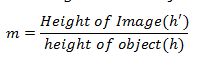
Magnification produced by a spherical mirror gives the relative extent to which the image of an object is magnified with respect to the object size. It is expressed as the ratio of the height of the image to the height of the object. It is usually represented by the letter m. So,
or,
\(m = \frac{{{h_1}}}{{{h_2}}}\)
The magnification m is also related to the object distance (u) and image distance (v) and is given as
\(m = \frac{{{h_1}}}{{{h_2}}} = - \frac{v}{u}\)
Refraction of light
We know about light and also know that light travels in a straight line path in a medium or two different mediums with same density.
Now a question arises what happens when light travels from one medium to another with different densities for example from air to glass.
When light ray is made to travel from one medium to another say from air to glass medium then light rays bend at the boundary between the two mediums.
So, the bending of light when it passes from one medium to another is called Refraction of light.
The refraction of light takes place on going from one medium to another because the speed of light is different in two media.
Medium in which speed of light is more is called optically rarer medium and medium in which speed of light is less is known as optically denser medium. For example glass is an optically denser medium than air and water.
NOTE:- When light goes from rarer medium to denser medium it bends towards the normal and when it goes from denser medium to rarer medium it bends away from the normal.
Refraction through a rectangular glass slab
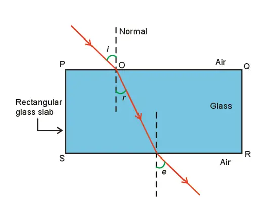
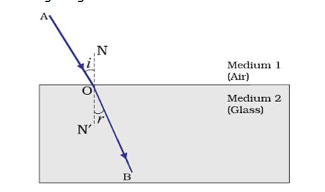
To understand the refraction of light through a glass slab consider the figure given below which shows the refraction of light through a rectangular glass slab.
Here in this figure AO is the light ray traveling in air and incident on glass slab at point O.
Now on entering the glass medium this ray bends towards the normal NN’ that is light ray AO gets refracted on entering the glass medium.
After getting refracted this ray now travels through the glass slab and at point B it comes out of the glass slab as shown in the figure.
Since ray OB goes from glass medium to air it again gets refracted and bends away from normal N1N'1 and goes in direction BC.
Here AO is the incident ray and BC is the emergent ray and they both are parallel to each other and OB is the refracted ray.
Emergent ray is parallel to incident ray because the extent of bending of the ray of light at the opposite parallel faces which are PQ (air-glass interface) and SR (glass-air interface) of the rectangular glass slab is equal and opposite.
In the figure i is the angle of incidence, r is the angle of refraction and e is the angle of emergence.
Angle of incidence and angle of emergence are equal as emergent ray and incident ray are parallel to each other.
When a light ray is incident normally to the interface of two media then there is no bending of light ray and it goes straight through the medium.
Laws of refraction of light(Snell’s law of refraction)
Refraction is due to change in the speed of light as it enters from one transparent medium to another.
Experiments show that refraction of light occurs according to certain laws.
So Laws of refraction of light are
The incident ray, the refracted ray and the normal to the interface of two transparent media at the point of incidence, all lie in the same plane.
The ratio of sine of angle of incidence to the sine of angle of refraction is a constant, for the light of a given color and for the given pair of media. This law is also known as Snell’s law of refraction.
If i is the angle of incidence and r is the angle of refraction then
\( \frac{\sin i} {\sin r} = constant = n \) (1)
This constant value is called the refractive index of the second medium with respect to the first.
The Refractive Index
We now know about refraction of light and the extent of the change in direction that takes place in a given pair of media is expressed in terms of the refractive index, the "constant" appearing in equation 1.
The refractive index is related to an important physical quantity that is relative speed of propagation of light in different media as light propagates with different speeds in different media.
Consider the figure given below
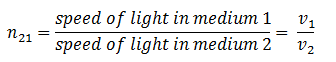
Let v1 be the speed of light in medium 1 and v2 be the speed of light in medium 2 then the refractive index of medium 2 with respect to medium 1 is given by the ratio of the speed of light in medium 1 and the speed of light in medium 2. So,
where n21 is the refractive index of medium 2 with respect to medium 1.
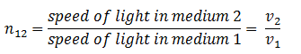
The refractive index of medium 1 with respect to medium 2 is represented as n12. It is given by
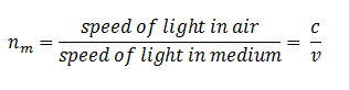
If medium 1 is vacuum or air, then the refractive index of medium 2 is considered with respect to vacuum. This is called the absolute refractive index of the medium.
If c is the speed of light in the air and v is the speed of light in any medium then refractive index nm of the medium would be
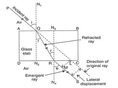
Prove that the incident angle and the emergent angle in a rectangular glass slab are equal
Figure :- Refraction of light through rectangular glass slab
In the figure given above ABCD is a rectangular glass slab of thickness AD=BC=t. A ray PQ is incident on it an face AB at point Q, making an angle $PQN_1=i$, called angle of incidence.
This ray refracts in the glass slab and goes along QR as refracted ray (as shown in the figure) and becomes incident on face DC at point R from inside the slab.
$\angle RQ{{N}_{2}}=\angle QR{{N}_{3}}=r$ and is called angle of refraction.
Now the ray emerges or comes out of the slab along RS making $\angle SR{{N}_{4}}=e$ , called the angle of emergence.
This emergent ray is parallel to the incident ray. This can be proved as follows.
For refraction of Q :- from air to glass
\begin{equation*}
n=\frac{\sin i}{\sin r}
\end{equation*}
For refraction at R :- from glass to air
\begin{equation*}
\frac{1}{n}=\frac{\sin r}{\sin e} \tag{1}
\end{equation*}
or,
\begin{equation*}
n=\frac{\sin e}{\sin r} \tag{2}
\end{equation*}
from equations 1 and 2
\begin{align*}
& \sin i=\sin e \\
& \Rightarrow i=e \\
\end{align*}
angle of incidence = angle of emergence
It means that incident ray and emergent ray makes equal angles with parallel normal ${{N}_{1}}Q{{N}_{2}}$ and ${{N}_{3}}R{{N}_{4}}$ . Hence incident and emergent rays are parallel.
Refraction by Spherical Lenses
A Spherical lens is a piece of transparent glass bound by two spherical surfaces.
There are two types of Spherical Lenses
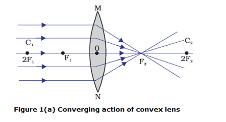
A convex lens bulges outward and is thick at the center and thinner at the edges. Convex lens converges the light rays as shown below in the figure 1(a). Hence convex lenses are called converging lenses.
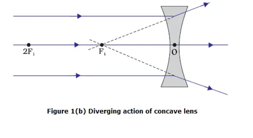
A concave lens bulges inward and is thinner in the middle and thicker at the edges. Such lenses diverge light rays as shown in Figure 1(b) Such lenses are called diverging lenses.
A lens, whether it is a convex lens or a concave lens, has two spherical surfaces which form a part of a sphere. The centers of these spheres are called centers of curvature of the lens usually represented by the letter C.
Since there are two centers of curvature, we may represent them as C1 and C2.
An imaginary straight line passing through the two centers of curvature of a lens is called its principal axis as shown in figure 1.
The central point of a lens is its optical centre. It is usually represented by the letter O.
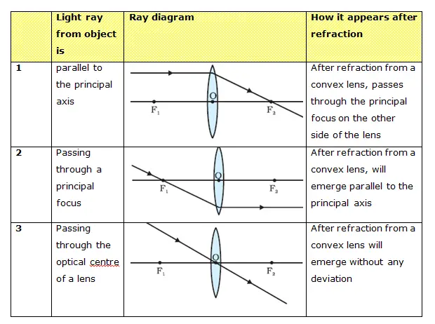
A ray of light through the optical centre of a lens passes without suffering any deviation.
The effective diameter of the circular outline of a spherical lens is called its aperture.
In figure 1 (a) you can see several rays of light parallel to the principal axis are falling on a convex lens. These rays, after refraction from the lens, are converging to a point on the principal axis. This point on the principal axis is called the principal focus of the lens.
Letter F is usually used to represent principal focus. A lens has two principal foci.
Similarly in figure 1 (b) several rays of light parallel to the principal axis are falling on a concave lens. These rays, after refraction from the lens, are appearing to diverge from a point on the principal axis. This point on the principal axis is called the principal focus of the concave lens.
The distance of the principal focus from the optical centre of a lens is called its focal length represented by letter f .
Image Formation by Lenses
Lenses form images by refraction of light and type of image formation depends on the position of the object in front of the lens.
We can place the objects at
Infinity
Beyond 2F1
At 2F1
Between F1 and 2F1
At focus F1
Between focus F1 and optical center O
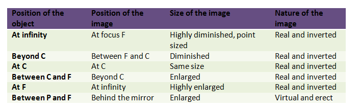
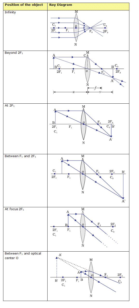
Image formation by a convex lens for different positions of the object is shown below in the table
Position of the object
Position of the image
Relative size of the image
Nature of the image
Infinity
At focus F2
Highly diminished, point sized
Real and inverted
Beyond 2F1
Between F2 and 2F2
Diminished
Real and inverted
At 2F1
At 2F2
Same size
Real and inverted
Between F1 and 2F1
Beyond 2F2
Enlarged
Real and inverted
At focus 2F1
At infinity
Infinitely large or highly enlarged
Real and inverted
Between F1 and optical center O
On the same side of the lens as the object
Enlarged
Virtual and erect
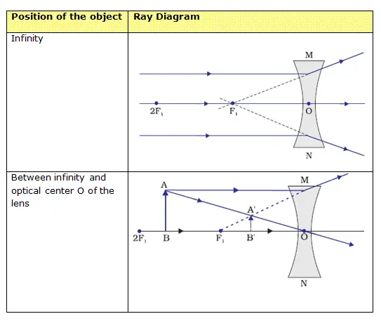
Nature, position and relative size of the image formed by a concave lens for various positions of the object is given below in the table
Position of the object
Position of the image
Relative size of the image
Nature of the image
At infinity
At focus F
Highly diminished, point-sized
Virtual and erect
Between infinity and optical center O of the lens
Between F1 and optical center O
Diminished
Virtual and erect
A concave lens will always give a virtual, erect and diminished image, irrespective of the position of the object.
Image Formation in Lenses Using Ray Diagrams
Ray diagram helps us to study the nature, position and relative size of the image formed by lenses.
For drawing ray diagrams we first consider how light rays falling on both concave and convex lens in three different ways get refracted.
First consider the case for convex lens
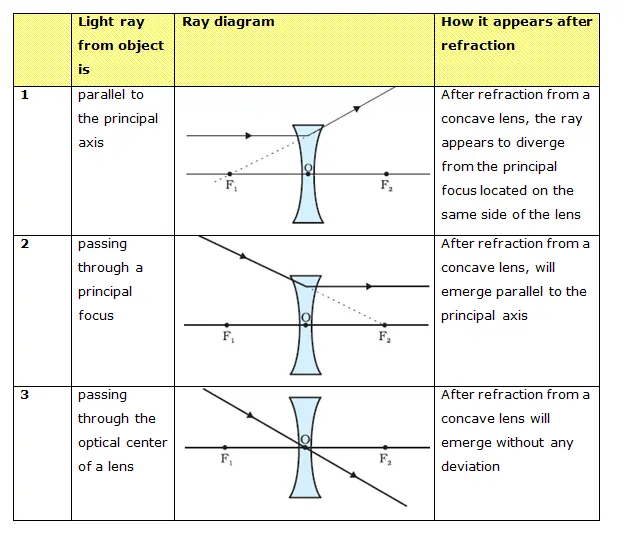
Secondly consider the case for concave lens
The ray diagrams for the image formation in a convex lens for a few positions of the object are summarized below in the table
The ray diagrams for the image formation in a concave lens for a few positions of the object are summarized below in the table
Sign Convention for Spherical Lenses
All the distances are measured from the optical center of the lens.
The distances measured in the same direction as that of incident light are taken as positive.
The distances measured against the direction of incident light are taken as negative.
The distances measured upward and perpendicular to the principle axis are taken as positive.
The distances measured downwards and perpendicular to principle axis is taken as negative.
Lens Formula and Magnification
Lens Formula gives the relationship between object distance (u), image image-distance (v) and the focal length (f ) and is expressed as
\( \frac{1}{f} = \frac{1}{v} - \frac{1}{u} \)
This formula is valid in all situations for any spherical lens.
The magnification produced by a lens is defined as the ratio of the height of the image and the height of the object.
Magnification produced by a lens is also related to the object-distance u, and the image-distance v and is given by
\( m = \frac{v}{u} \)
The power of a lens is defined as the reciprocal of its focal length. It is represented by the letter P. The power P of a lens of focal length f is given by
\(P = \frac{1}{f}\)
Power of a convex lens is positive and that of a concave lens is negative.
The SI unit of power of a lens is ‘diopter’. It is denoted by the letter D.
1 diopter is the power of a lens whose focal length is 1 meter so, \(1D=1m^{–1}\).