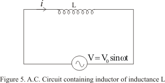
Figure below shows the circuit in which voltage source
V=V0sinωt (10)
is applied to pure inductor (zero resistance) coil of inductance L
As the current through the inductor varies and opposing induced emf is generated in it and is given by -Ldi/dt
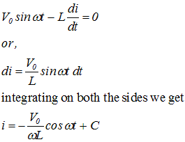
From Kirchhoff�s loop rule
Where C is the constant of integration .This integration constant has dimensions of current and is independent of time. Since source has an emf which oscillates symmetrically about zero, the current it sustain also oscillates symmetrically about zero, so there is no time independent component of current that exists. Thus constant C=0
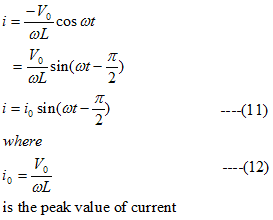
So we have
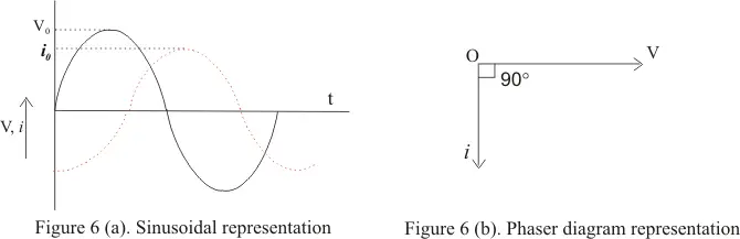
From instantaneous values of current and voltage (equation 11 and 10) we see that in pure inductive circuit the current lags behind emf by a phase angle of π/2
This phase relationship is graphically shown below in the figure
From equation (12) peak value of current in the coil is
i0=V0/ωL
or
V0=(ωL)i0
Comparing it with the ohm's law we find product ωL has dimension of resistance and it can be represented by
XL=ωL
where XL is known as reactance of the coil which represents the effective opposition of the coil to the flow of alternating current
XL=ωL is zero for DC for which ω=0 and increases as the frequency of current increases