Circuit containing inductance and resistance in series|Alternating Current
Circuit containing inductance and resistance in series
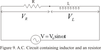
Figure below shows pure inductor of inductance L connected in series with a resistor of resistance R through sinusoidal voltage
V=V0sin(ωt+φ)
An alternating current I flowing in the circuit gives rise to voltage drop VR across the resistor and voltage drop VL across the coil
Voltage drop VR across R would be in phase with current but voltage drop across the inductor will lead the current by a phase factor π/2
Now voltage drop across the resistor R is
VR=IR
and across inductor
VL=I(ωL)
where I is the value of current in the circuit at a given instant of time
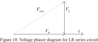
So voltage phasors diagram is
In figure (10) we have taken current as a reference quantity because same amount of current flows through both the components. Thus fro phasors diagram
is known as impedance of the circuit
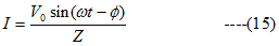
Current in steady state is
and it lags behind applied voltage by an angle φ such that
tanφ=ωL/R ---(16)