Circuit containing Capacitor and resistance in series|Alternating Current
Circuit containing capacitance and resistance in series
- Figure below shows a circuit containing capacitor and resistor connected in series through a sinusoidal voltage source of voltage
V=V0sin(ωt+φ)
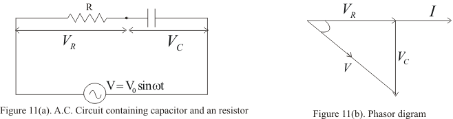
- In this case instantaneous P.D across R is
VR=IR
and across the capacitor C is
VC=I/ωC
- In this case VR is in phase with current i and VC lags behind i by a phase angle 900
- Figure 11(b) shows the phasors diagram where vector OA represent the resultant of VR and VC which is the applied Voltage thus
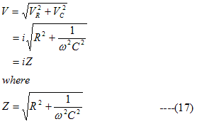
is called the impedance of the circuit
- Again from the phasors diagram applied voltage lags behind the current by a phase angle φ given by
tanφ= VC/ VR=1/ωCR ---(18)