Phasor diagrams for AC circuits
Phasor diagram
- Phasor diagrams are diagram representing alternating current and voltage of same frequency as vectors or phasors with the phase angle between them
- Phasors are the arrows rotating in the anti-clockwise direction i.e. they are rotating vectors but they represents scalar quantities
- Thus a sinusoidal alternating current and voltage can be represented by anticlockwise rotating vectors if they satisfy following conditions
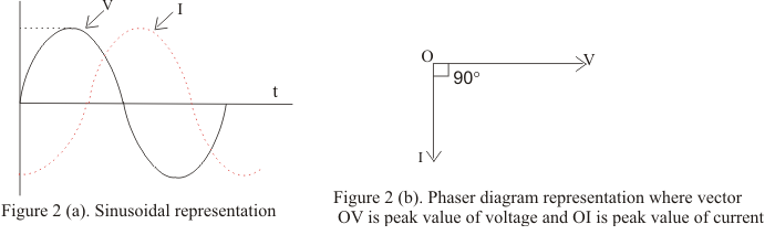
- Length of the vector must be equal to the peak value of alternating voltage or current
- Vector representing alternating current and voltage would be at horizontal position at the instant when alternating quantity is zero
- In certain circuits when current reaches its maximum value after emf becomes maximum then current is said to lag behind emf
- When current reaches its maximum value before emf reaches its maximum then current is said to lead the emf
- Figure below shows the current lagging behind the emf by 900