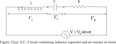
Figure below shows a circuit containing a capacitor ,resistor and inductor connected in series through an alternating voltage source
Same amount of current will flow in all the three circuit components and vector sum of potential drop across each component would be equal to the applied voltage
If i be the amount of current in the circuit at any time and VL,VC and VR the potential drop across L,C and R respectively then
VR=iR ⇒ Voltage is in phase with i
VL=iωL ⇒ Voltage is leading i by 900
VC=i/ωC ⇒ Voltage is lagging behind i by 900
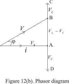
Since VL is ahead of i by 90 and VC is behind by 90 so that phase difference between VL and VC is 180 and they are in direct opposition to each other as shown in the figure 12(b)
In figure 12(b) we have assumed that VL is greater than VC which makes i lags behind V.If VC > VL then i lead V
In this phasors diagram OA represent VR,AD represent VC and AC represent VL.So in this case as we have assumed that VL > VC ,there resultant will be (VL -VC) represented by vector AD
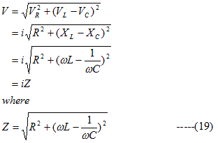
Vector OB represent resultant of vectors VR and (VL -VC) and this vector OB is the resultant of all the three ,which is equal to applied voltage V,thus
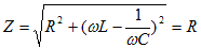
is called impedance of the circuit
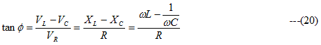
From phasors diagram 12(b),current i lag behind resultant voltage V by an phase angle given by,
From equation (20) three cases arises (i) When ωL > 1/ωC then tanφ is positive i.e. φ is positive and voltage leads the current i (ii) When ωL < 1/ωC,then tanφ is negative i.e. φ is negative and voltage lags behind the current i (iii) When ωL = 1/ωC ,then tanφ is zero i.e. φ is zero and voltage and current are in phase
Again considering case (iii) where ωL = 1/ωC,we have
which is the minimum value Z can have.
This is the case where XL=XC,the circuit is said to be in electric resonance where the impedance is purely resistive and minimum and currents has its maximum value
Hence at resonance
ωL = 1/ωC
or ω=1/√LC ---(21)
But ω=2πf where f is the frequency of applied voltage .Therefore
f0=1/2π√LC ---(22)
This frequency is called resonant frequency of the circuit and peak current in this case is
i0=V0/R
and reactance is zero
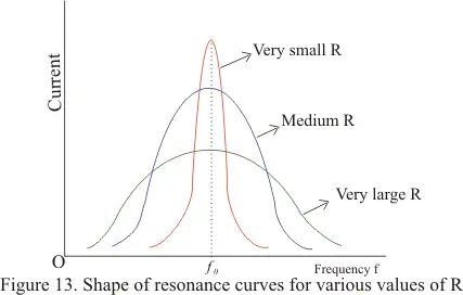
We will now define resonance curves which shows the variation in circuit current (peak current i0) with change in frequency of the applied voltage
Figure below shows the shape of resonance curve for various values of resistance R
for small value of R,the resonance is sharp which means that if applied frequency is lesser to resonant frequency f0,the current is high otherwise
For large values of R,the curve is broad sided which means that those is limited change in current for resonance and non -resonance conditions